Thursday 15 December 2016

Atari - Video Pinball High Score Save Mod

So we all know on UkVac PhilMurr is the king of High Score Save modding with Hardware and software mods allowing all sorts of trickery to take place with our vintage games. 

Now I can't remember when we discussed the idea of a High Score save mod for Video Pinball but I do remember telling Phil it would be a good addition to the game. The high score is displayed during attract mode, there's no table for initials; just a single entry showing the best players score.

So after discussing with Phil we initially thought we could get things done by using his 6502 ROM & RAM board along with some coding magic. After various attempts with the code and changing the way the 6502 board could be used we (and really I mean Phil!) got the board running the game without the need to use any other game ROMs, they were all running happily from the 6502 mod board. 

To make the high score persistent through a power down another hardware mod was going to be needed. The two rams where the score is stored are 2114's at location C3 & F3 on the Game PCB. Phil already had a RAM board that takes two 2114 RAMs and uses a 6116 in its place combined with a coin cell battery and a Non volatile Controller IC to save scores on the game Phoenix, this was going to be our weapon of choice to solve the problem. due to the IC locations on the Video Pinball PCB it wasn't going to plug directly in, I needed to have four wires from the data lines on the RAM PCB linking into one of the RAM locations on the game PCB. 

I used some SIL header pins so the mod is fully removable, I soldered the link wires into the SIL headers and these plug into the sockets for the RAM.

There's a few photos below showing how the mod fits the Game PCB.

I'm sure Phil can comment on the intricacies of the mod if anyone has any questions.

I'm really pleased with this mod and owe Phil a few beer tokens for his efforts in getting this up and running. 

Cheers, Mart.


Saturday 3 December 2016

Atari Breakout PCB repair. W.I.P Part 3

Part 3

So cleaning the are around the IC that had failed showed no real track damage, the board is burnt and doesn't look pretty but nothing is shorting together or in need of repair.


I fitted a new socket and replaced the 7432. Upon powering the game up the video tearing I was previously seeing has gone there's still some sort of image issue on the left side, and the bouncing ball has appeared. Progress is being made. :)

The ball was just running from the bottom of the display to the top and repeating over and over. No collision detection or rebounding with the bricks or side walls.


Now then, the paddle wasn't looking correct, It would change size when you turn the spinner but didn't really move correctly. In the paddle circuit I found a 7408 that had a bad output on pin 11. This was swapped out with a replacement and as shown below the paddle now works correctly, even though it is too small. The ball will now rebound off the paddle in game mode or in attract mode, it will also rebound off the top wall above the score line so it's not detecting the bricks.


Clearly there are issues with the game coming in & out of attract mode, the scoring isn't working correctly and I'm sure the amount of live isn't being counted correctly and I haven't even looked at the sound circuits yet.

There's still plenty more to fix by the looks of it. I'll keep you all updated.
 

Atari Breakout PCB repair. W.I.P Part 2

Part 2

Following on from my last session looking at the Breakout PCB, I spent a short while making the wiring connection more complete on the edge connector. I added Coin 1, 1 Player start, Serve and the paddle control. I also added a link to the edge connector for Coin 2; on these early games the coin switches use a common connection along with a normally open and a normally closed contact. If the normally closed contact connection of Coin2 isn't connected to the games common ground connection the game will always think the in Coin2 switch is being activated and stuck on usually stopping you from coining the coining up properly or playing the game correctly.


I decided to begin this session by checking all the the H & V clock signals that are divided down from the master clock circuit on the PCB. They all appear correct and present when using a logic probe to check for signals at the IC's where they are created (K1,L1,N1,N1 9316 IC's).

Next up I look at one of the Rams at L3 just checking for signals, no real idea of thinking about a fix just checking components that could lead to finding a fault; well its missing one of the Chip Enable signals on pin 3, not a high signal, not a low, nothing. Taking a look at the board (even though I already made a quick visual check) it's clear there's a broken trace, most likely from the original multiple wire mod that had been installed at some point.

Image below shows the offending broken trace.  


I checked where this was wired and sure enough one side of the broken trace was connected to pin 3 of the IC that had the missing signal.

I made a repair using an old cut off capacitor leg. shown below.


Powering up the game I'm now presented with some Playfield bricks :)


So in my mind now other than the bad video syncing/tearing issue, the game when in attract mode is missing a bouncing ball along with a paddle 'wall' which should completely cover the bottom part of the screen in attract mode. There is a 74157 IC which controls these component parts of the video graphics, before they are joined to a resistor network to make the final video signal.
The  *Pad signal is missing, again using a bright light to investigate another trace is broken (to the left of the middle IC in the photo below)


Once this is repaired we appear to have a paddle at the bottom of the screen, not completely covering the horizontal plane but good enough for now until I have fixed the bad syncing if the video.


I thought I'd try and find why the ball was not visible, it should be bouncing around the screen in attract mode. There is a signal called 'BALL' this was active, it passed through a circuit linked to the serve button on the control panel and the signal turns into 'BALLL DISPLAY' this signal is stuck low.

Tracing though this part of the circuit I find the 'Serve' signal (derived from the control panel button) is constantly stuck low even when the switch isn't connected, the signal should be 'high' when the serve switch is 'open'.

More signal tracing goes on which leads to a 7432 at location D2 looking at the image below you can see the area around pin 12 look a bit brown and burnt. It turns out pins12 a logic input is directly shorted to pin 11 an input. Also the track in between pins 11 & 12 was shorted to these two pins! That trace is a signal connected to the coin switch circuit. Considering pin 12 is connected to the serve switch I can only guess that at some point someone has put voltage down this connection instead of the serve switch wiring


I decide to chop this pin out to see what's going on with the burnt looks around this IC. After snipping the leg off, I'm greeted with the following mess! This IC has failed big time with parts of it melting to the track below the IC.


This area needs to be cleaned up and checked over before replacing the IC and hopefully seeing the Ball bouncing around the screen.

To Be Continued...

Tuesday 29 November 2016

Atari Breakout PCB repair. W.I.P

Part 1

So I was given this Breakout PCB at Steve's meet by Backflipper [another Steve :) ] earlier in the year and thought I'd fire it up and see if it worked.


First up the PCB was covered in lots of wires that were soldered onto the board but with nothing connected to them, some sort of previous mod that had been removed.


I de-soldered these wires and re-made a trace that had been cut on the PCB.

Visually there were a few IC's missing and one that was broken almost in half and partially de-soldered. After looking up the IC locations in the Ops manual, all three were 74LS08's, clearly someone needed them for something else! The solder pads were cleaned, new sockets fitted and IC's fitted.


Next up was the big filter Capacitor near the edge connector. This was clearly past its best so I replace it with another I had in my stash.


There were four wire links on the board which denote the game bonus given depending on score. These were a right mess where I guess they had previously been moved around. I removed the links and fitted a nice new 4-way dip switch block similar to what all the later Atari games have.


Next up it was time to make a basic loom to apply power and get some composite video out of the game.

Looking at the high level wiring diagram for the game, the power input comes from a 16.5Vac centre tapped transformer, which via a couple of diodes feeds the audio amplifier and then into an LM323 regulator which provides the regulated 5Vdc for the game logic.

From previous experience with these old Atari Black & White games I know you can happily run these games from a 12Vdc power supply as long as it supplies 3 Amps of current if the have an LM323 regulator.. Most JAMMA switcher supplies wont work as they don't provide enough current on the 12V rail. With power connections made to an edge connector I looked up the pins for the Video output and it's ground connection and wired these to a phono (RCA) connector which would plug into my video monitor.

With only these connections made I should be able to see if the board is dead or alive, or somewhere in between.

One final check I decided to make was to confirm that the 5V rail and the Ground rail on the PCB were not shorted to each other, this was confirmed as being OK with my Multi-meter set on continuity test.

Time to fire it up!

So with monitor connected to the video cable and the edge connector plugged into the PCB I powered it up...


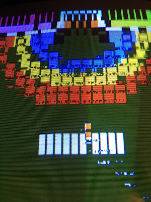
Not bad... The board has a video output, which is stable apart from some image tearing on the right hand side, I'll need to confirm if this is a fault with the PCB or if my monitor is struggling to sync to the signal.

You can see the score numbering along with the numbers indicating which player is 'up' and which ball is is in play. There are clearly not correct, but the fact they're being show is a good sign.

There's no playfield of bricks, a players paddle or any balls flying around the screen so the board at this point so I need to investigate further to see whats going on.


So next up I need to make connections for controls, and coins switches etc, then I'll print the schematics and get out my trusty Logic probe.

Tuesday 27 September 2016

Sega Hang-On PCB Repair

So my Hang On cab broke down when I loaned it to the last Revival show earlier in the year.... The game had been totally reliable for approximately 15 years prior to its journey to the show, well after being powered on for the morning the monitor image turned to garbage, foreground text was still visible, but the majority of graphics were a garbled mess and the game wouldn't actually start.


Tonight I fixed the game. First I confirmed the fault was on the CPU board, Hang-On comprises of a four board set which includes the mention CPU board, a Control/Video board and a ROM and Sound board. The game will run with Just the CPU and Control board connected, this makes it slightly easier to test whilst hanging out of that back of my cab! There are sprites and graphics missing and no sound but the game will run.

I knew the CPU ROM's and CPU RAM were working OK, The ROMS were verified and the RAM had previously been socketed so it was easy to confirm they were good.

Using my trusty logic probe I could see there was plenty of active logic across the CPU board, After looking the board over I homed in on a bank of Fujitsu 74LS157's, The Fujitsu IC's from this era of games have a reputation for going bad. Reading the schematic my understanding is that these bank of five 157's control the Address bus between the Main and Sub CPU's. All the inputs and output had active logic signals but select signal on pin 1 which decides which address bus signal should be active was stuck in a high state.


Tracing this back in the schematic, the signal comes from an LS109, Pin 3 the 'K' input was not showing as having any signal, again this was traced back to a 74LS32 at 8J (Labelled as 8H on the schematic!) Input pins 4 and 5 were active and pulsing away with data but the Output pin was showing no signs of life.. A quick piggyback test with a new 74LS32 proved this was the fault as the game screen came back good.

I removed and replaced the IC and the game is back in action.

Brmmmmm Brmmmmmmm!!! :)

Sunday 28 August 2016

Sega System 24 - Super Master Golf - swapping CPU battery


Sega System 24 boards were included in Sega's copy protection measures, this included a custom 68000 CPU that included a battery and some RAM which I believe stores code which is needed for the game to run. If the battery goes flat, (they're generally over 20 years old now) the game will not run. Certain games have had the game code 'cracked' to enable the use of a regular 68000 CPU by having to use re-programmed CPU ROMs. This is not possible with System 24 games so I needed to take some action to maximise the chance of my Golf Masters game working for the longest period of time possible.

Below, the Custom Sega IC


Old battery removed, with a new replacement in place... NOTE: You need to keep a battery connected at all time by wiring the new battery in parallel and then cutting the old battery out of circuit. This will ensure you don't end up with a IC that's only use will be disposing of in the bin!


The Original battery was date stamped 1989 and had started to corrode so I think my timing was right with this one. The battery still measured 3 volts dc with a multi meter, the nww battery was sitting at 3.25 volts.

One the CPU was put back into the game PCB it was still working which for now is a good sign :)


Bookkeeping info from the game, closing in on 7000 credits since the info was last reset with the game being played for 305 hours.


 Attract mode screen shot of the game playing below.


The next part of this story will cover how I used a floppy disk drive replacement device to replace the old Floppy drive and disk that were not working when I picked the cab up.


Monday 15 August 2016

Taito Field Goal - PCB Repair

I recently picked up a Taito Field Goal cocktail cabinet, upon powering up the game was showing a graphical fault. The game played correctly when coined up, but every graphical item or text were just blocks of colour. The image below shows how it looked.


After using my logic probe running over the video section of the PCB I found what I though could be an issue. The MB14241 custom IC had data being fed into it and the clocking/enable signals all seemed to be pulsing away, but all of the Data Output pins were not showing as having any signals on them.

Reading online about the Custom IC I found mention of it having tri-state outputs which could have been the reason my IC didn't show any activity. The IC in question is a video shifter which was used to assist with drawing of sprites in early Taito and Midway games.

Part of the schematic diagram shown below which includes the Custom IC which i suspected was faulty, The scan of the original schematic is difficult to read, the IC pin numbers are very blurry which makes working out issues more time consuming.


Whilst probing around i put my logic probe on pin24 which is the supply voltage pin, the pin snapped off from the IC! Clearly it was weak and corroded, I filed the IC down to expose the contact so I could solder my own 'IC leg' back on. I was hoping this would have been the issue, no supply voltage to the IC would match up with all the output pins being 'dead'.

Well this didn't fix the problem but the image of the display slightly changed. A couple of the output pins were now stuck high or low but most were still showing as being 'dead'.


My next option was to swap the IC with a known worker to see if this was the issue, luckily the custom was already socketed so I just needed to find a replacement and plug it in. Cue me asking a collector friend for a loan if he had one, luckily a Zenitone Invader Revenge PCB was found that had the same IC needed.

Once popped into my PCB the game fired and and played perfectly! I now need to procure a replacement IC and return the loaned IC.


Another 35 year old game lives on to be played!

Sunday 14 August 2016

Sega system 24 - Super Masters Golf

A cab I picked up recently. Looks like it has a faulty floppy disk as the game fails to load with error 'cannot read track #0'


Tuesday 9 August 2016

Super Breakout Cocktail restoration

I picked up three Super Breakout cocktails in part of the UKVAC Pete 'Invader' Davies machine collection which I'm sure you all know about know. Tony Temple has written a great article over at arcadeblogger.com if you would like more info on the back story of these cabs.

As it turned out there were three Super Breakout Cocktail's that ended up coming back in the van along with my other cabs. I've got a soft spot for B&W arcade games and these cab definitely sparked interest that I could do something with them.

After getting the cabs home and looking them over it looks like two of the three cabs can be saved and restored. I plan to restore one cab, with the other two being offered for someone else to restore. The first picture shows cabs that I'll call number two & three. These two are available if you fancy a project, the only requisite is that one of them does get restored and they are not left to rot away. More on these two cabs later.

This first post is just a selection of photos from the cabs in their 'stored' condition. As the restoration moves on I will update this thread with my progress.


Onto the cab that I will be restoring, they appear to be bootleg/licensed cabinets made by Bonanza Enterprises. Ever heard of them?


Monitor mounted to the tabletop lid, supported by a metal by which is mounted in the main cab.


Small amount of mould to be cleaned up.


Player 1 controls


Slightly cleaned up.


Player 2 controls


Top glass player instructions


More to come as I make any progress.

Cheers, Mart.